Rtl Nor Gate The Output Is At Logic 1 Only When All The Inputs Are At : Digital Logic NOR Gate(Universal Gate) - All About Engineering : In general, there is only one output to a logic gate except in some special cases.
Dapatkan link
Facebook
X
Pinterest
Email
Aplikasi Lainnya
Rtl Nor Gate The Output Is At Logic 1 Only When All The Inputs Are At : Digital Logic NOR Gate(Universal Gate) - All About Engineering : In general, there is only one output to a logic gate except in some special cases.. This idea is taken to the extreme in the classic dl, dtl. The output of an xnor gate is high only if the number of high inputs is even. (not certain). The output is high (1) only when all the inputs are low (0). The output of a nor gate is true all of its inputs are false. This schematic operates on the 5v supply vcc.
There is always a time delay between an input being applied and the output responding. For 0 and 0 we get a value of 1. Increasing the number of mosfets in parallel can potentially. Logic gate nand most logic gates have two inputs and one output. The truth table again looks as i described!
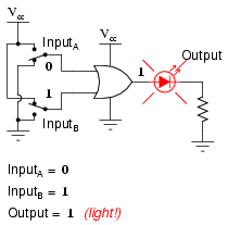
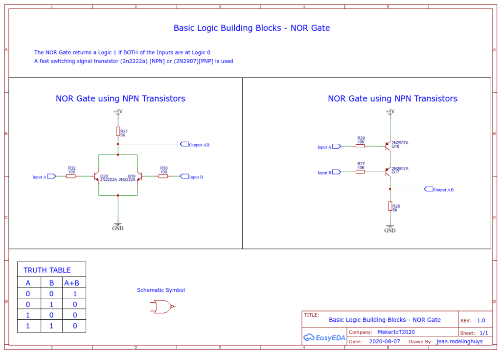
Multiple-input Gates | Logic Gates | Electronics Textbook from sub.allaboutcircuits.com A nor gate (sometimes referred to by its extended name, negated or gate) is a digital logic gate with two or more inputs and one output with behavior that is the opposite of an or gate. Any 1 on an input gives a 0 at the output. Thus the output becomes logic low. Rtl nor gate behaves as nor gate and the output of nor gate will be 1 only when all the inputs are at logic 0 and in rest answer: Weryl nor gate the output in at logic i only when all the inputs are of select ond. Nor gate is a digital logic gate (also known as universal gate) which gives output 1 only and only when all of its inputs are logic low state 0. Here we will cover : A basic circuit of an rtl nor gate consists of two transistors q1 and q2, connected as shown in figure above.
Why use only nand gates or only nor gates?
The truth table of a 2 input nor gate can be represented as Truth tables list the output of a particular digital logic circuit for all the possible combinations of its inputs. This idea is taken to the extreme in the classic dl, dtl. Logic gate nand most logic gates have two inputs and one output. The output of the nor gate is high if and only if both of its inputs are low otherwise its output is low, note that the nor gates are available in the ic packages. The output of an xnor gate is high only if the number of high inputs is even. (not certain). At any given moment, every terminal is in one of the two binary conditions low (0) or high (1), represented by different voltage levels. Gates have two or more inputs, except a not gate which has only one input. The nor gate is a combination of the digital logic or gate and an inverter or not gate connected together in series. The input logic variables turn on (at logic 1) or turn off (at logical 0) equal reference resistances (conductances). When either of these voltage levels is applied to the inputs, the output of the gate responds by assuming a 1 or a 0 level, depending on the particular logic of the gate. Still, the same logical principle applies: A nor gate (sometimes referred to by its extended name, negated or gate) is a digital logic gate with two or more inputs and one output with behavior that is the opposite of an or gate.
A nor gate's output is high only when both the inputs are low. For example, an and gate gives an output of logic 1 when input a and input b are at logic 1, but a nand gate would give a. In all the other cases, its output is low. The output is high (1) only when all inputs are low (0). The next step is to create the truth table.
Logic Building Blocks - The Logic Gates - Maker and IOT Ideas from www.makeriot2020.com Gates have two or more inputs, except a not gate which has only one input. A basic circuit of an rtl nor gate consists of two transistors q1 and q2, connected as shown in figure above. 7:52 me and my craft ideas 40 665 просмотров. The output of an xnor gate is high only if the number of high inputs is even. (not certain). In nor gate we get a high value of the output only when its input has a low value. We start with all of the input combinations presented as a standard binary count as illustrated in observe the two 1s highlighted in the image below. The truth table of a 2 input nor gate can be represented as Why use only nand gates or only nor gates?
The truth table again looks as i described!
Truth tables list the output of a particular digital logic circuit for all the possible combinations of its inputs. The input logic variables turn on (at logic 1) or turn off (at logical 0) equal reference resistances (conductances). One of the limitations of rtl circuits was that while nor gates are easy to construct, it is difficult to obtain a nand function in a single gate. The output of an xnor gate is high only if the number of high inputs is even. (not certain). The truth table of a 2 input nor gate can be represented as It is equivalent to feeding the output through a not gate. This idea is taken to the extreme in the classic dl, dtl. They are summed by an analog so it is sufficient that only one reference is turned on and the output is set at logic state 1. Any 1 on an input gives a 0 at the output. Thus, the rtl nor gate shown in figure 1 becomes a dctl nor gate if all the base resistors (rb's) are eliminated. We know that this means the output is 1 in both these cases. Still, the same logical principle applies: When both of the inputs is logic high i.e.
They are summed by an analog so it is sufficient that only one reference is turned on and the output is set at logic state 1. A nor gate's output is high only when both the inputs are low. Nor gate has a minimum of 2 inputs and can have more than 2 inputs but it has only a single the schematic of nor gate in rtl logic is given below: The next step is to create the truth table. We can obtain nor logic by just connecting a not gate to an or gate.
NOR logic gate - Electronics Area from electronicsarea.com In nor gate we get a high value of the output only when its input has a low value. Increasing the number of mosfets in parallel can potentially. A nor gate's output is high only when both the inputs are low. The output is high (1) only when all the inputs are low (0). Gates have two or more inputs, except a not gate which has only one input. I am working out the ideal rtl nor circuit to use as universal gates for a large project. Truth tables list the output of a particular digital logic circuit for all the possible combinations of its inputs. Based on what i've found on wikipedia, to however, by connecting the outputs together they no longer have individual logic states and cannot be connected anywhere else and appear as the correct logic state.
In all the other cases, its output is low.
Nand is simpler and takes less parts than. Any 1 on an input gives a 0 at the output. The truth table again looks as i described! The input logic variables turn on (at logic 1) or turn off (at logical 0) equal reference resistances (conductances). Increasing the number of mosfets in parallel can potentially. The output of an xnor gate is high only if the number of high inputs is even. (not certain). 7:52 me and my craft ideas 40 665 просмотров. Still, the same logical principle applies: The truth table of a 2 input nor gate can be represented as It is equivalent to feeding the output through a not gate. They are summed by an analog so it is sufficient that only one reference is turned on and the output is set at logic state 1. 0v and 5v representing logic 0 and logic 1 respectively. Based on what i've found on wikipedia, to however, by connecting the outputs together they no longer have individual logic states and cannot be connected anywhere else and appear as the correct logic state.
Rtl nor gate behaves as nor gate and the output of nor gate will be 1 only when all the inputs are at logic 0 rtl nor gate. Some gate symbols have a circle on their output which means that their function includes inverting of the output.

Komentar
Posting Komentar